
In digital electronics a NAND gate NOT-AND is a logic gate which produces an output which is false only if all its inputs are true. The Boolean expression given for a NAND gate is that of logical addition and it is opposite to AND gate.
Nand Gate Digital Logic Gates Electronics Tutorial
Basic Logic Gates Using Nand Gate Not Or And Gates

What Are Logic Gates And Why Are They Important Electronics Point
When any one of the ips of the NOR gate is true then the output of the NOR gate will be false.
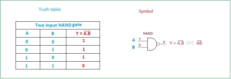
Nand gate truth table. The symbol of the NAND gate is represented as a. Types of Logic Gates. From the logic circuit the output can be expressed as.
As well as a standard Boolean Expression the input and output information of any Logic Gate or circuit can be plotted into a standard table to give a visual representation of the switching function of the system. The pins S and R are normally pulled down. From the truth table we can say that the output of the AND logic or an AND gate is True or high or 1 only when A and B are 1.
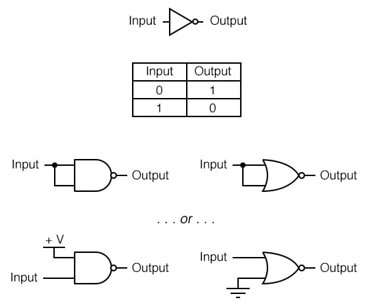
The truth table for a NOT gate appears to the right. Symbol and truth table of NAND gate. Thus its output is complement to that of an AND gateA LOW 0 output results only if all the inputs to the gate are HIGH 1.
The output of NAND gate is low 0 if all of its inputs are high 1. You can see that this is just the reverse of the truth table of an AND gate. A NOT gate produces an output that is the complement of the input.
Hence the truth table of a 2 input NAND gate can be represented as. The Boolean expression is given by a single dot with an overline over the expression to show the NOT or the logical negation of the NAND gate. The output of NAND gate is high 1 if at least one of its inputs is low 0.
It performs a basic logic function called inversion or. In such cases the same general principle applies. The output can only be low when both the inputs are.
For example the NAND Not AND gate symbol shown on the right is the same as an AND gate symbol but with the addition of an inverting circle on the output. Truth Table Generate is an online website you can Where you can create truth tables allows you to decide on variables and logical activities like your choice. Similar to 3-input NAND gates we can also design 4-input NAND gate.
If the truth table for a NAND gate is examined or by applying De Morgans Laws it can be seen that if any of the inputs are 0 then the output will be 1To be an OR gate however the output must be 1 if any input is 1. A pair of cross-coupled 2 unit NAND gates is the simplest way to make any basic one-bit setreset RS Flip Flop. NAND gateBubbled OR gate NAND Gate Truth Table.
Truth table is a table that gives output for all possible combinations of inputs to a logic circuit. Now when we give binary 1 at the input terminal we will get 0 at the output due to property of the NAND gate which can be seen from the truth table of the NAND gateIC7400 is been used by us which is a Quad two terminal input NAND gate. It forms SetReset bi-stable or an active LOW RS NAND gate latch.
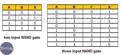
The output will be low 0 if and only if all inputs are high 1. Like AND gate a NAND gate can also be more than two inputs like 3 4 input NAND gate. The logic circuit of the NAND gate is shown below.
An OR Gate is an electronic circuit that gives a true output 1 if one or more of its input are true. DCode truth table generator interprets the Boolean logical expression and calculates using Boolean algebra all the possible combinations of 0 and 1 for each variable among the Boolean variables requested in order to convert the boolean expression and make the truth table. In other words if the input is true then the output will be falseSimilarly a false input results in a true output.
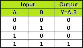
If you observe the table the equivalent mathematical logic for the AND boolean logic is that of multiplication. The output of the NAND gate is always at logic high1 and only goes to logic low0 when all the inputs to the NAND gate are at logic 1. Truth tables A truth table is a good way to show the function of a logic gate.
The output of the 3 input NAND gate is LOW when all the 3 inputs are HIGH and it will be HIGH for all other combinations of inputs. As with AND gates NAND gates are made with more than two inputs. Is used to show the OR.
A logic gate which performs the function of logical operator NOT is called as NOT gateSome of the function of NOT gate are as follow. A NOT gate often called an inverter is a nice digital logic gate to start with because it has only a single input with simple behaviorA NOT gate performs logical negation on its input. The equation is read as Z equals NOT A AND B.
A NAND gate is made using transistors and junction diodes. The NOR gate is a digital logic gate with n inputs and one output that performs the operation of the OR gate followed by the NOT gate. The interconnection of gates to perform a variety of logical operation is called logic design.
Now we will see the design of an AND gate from NAND gates. Here it is done using NAND gates. NAND Gate and its Truth Table NOR Gate.
The truth table of 3 input NAND gate is given below. The symbol and. The time sequence at right shows the conditions under which the set and reset inputs cause a state change and when they dont.
A NAND Gate is constructed by connecting a NOT Gate at the output terminal of the AND Gate. The truth table and corresponding states varies according to the type of construction which can be either using NAND gates or NOR gates. The above diagram is of an AND gate made from NAND gate.
Therefore if the inputs are inverted any high input will trigger a high output. A truth table lists all possible combination of inputs and the corresponding outputs. The table used to represent the boolean expression of a logic gate function is commonly called a Truth TableA logic gate truth table shows each possible input combination to the.
Truth table is a table which shows the shows the output state depending upon the possible combination of input statesIt shows the function of a logic gate. Hence default input state will be S0 R0. In other words we can say that the output of the NAND gate always continues true if at least one of its inputs remains false or logic low.
The figure-3 depicts OR logic gate symbol and table-3 below mentions truth table of OR gate. The truth table of an AND gate is given below for reference. All logic gates obey their truth table.
DCode also makes it possible to find the Boolean logic functionexpression from a truth table. If any input is LOW 0 a HIGH 1 output results. Table2 NAND gate truth table OR Logic Gate Symbol and Truth Table Figure3 OR gate logic symbol The OR gate is an electronic circuit which gives a true output1 if one or more of its inputs are true.
Since the logic circuit involves an AND gate followed by an inverter. The truth table of an OR gate is also given beside the diagram. Following the truth table for the S-R flip-flop a negative pulse on the R input drives the output Q to zero.
NOR gate is designed by combining the OR and NOT gate. Logic Symbol- The logic symbol for NAND Gate is as shown below- Truth Table- The. The feedback is fed from each output to one of the other NAND gate input.
The truth table for a NAND gate is as one might expect exactly opposite as that of an AND gate. A plus is used to show the OR operation. The NAND Gate RS Flip Flop.
The Logic NAND Gate function is sometimes known as the Sheffer Stroke Function and is denoted by a vertical bar or upwards arrow operator. 2Construction of AND Gate with NAND Gate. So we can see that all the three basic gates can be made by only using NAND gates thats why this gate is called Universal Gate and it is appropriate.
It has only one input signal.
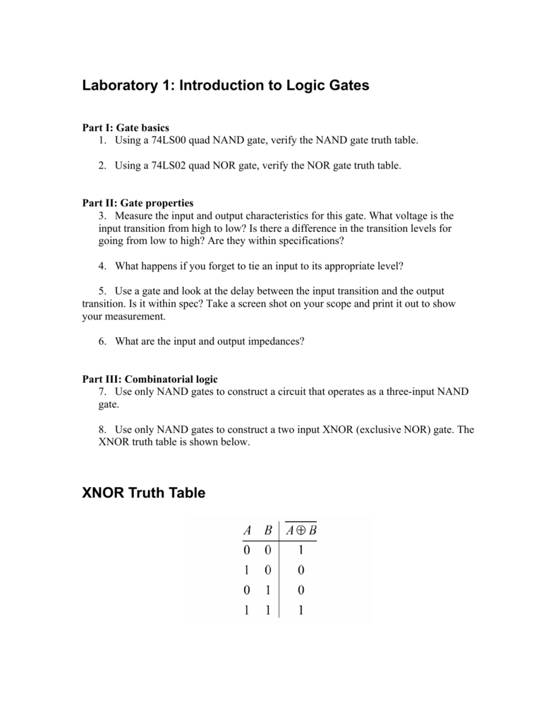
Laboratory 1 Introduction To Logic Gates Xnor Truth Table
Nand Nor Xor Logic Gates Video Lesson Transcript Study Com

Digital Electronics Basic Truth Tables
Gate Universality Logic Gates Electronics Textbook

This Is The Truth Table Of 3 Input And Gate Output Is High When Only All Inputs Are High In 2021 Logic Design Logic Nand Gate
Basic Logic Gates Truth Table
Nand Gate 2 Input 3 Input Truth Tables Electronics Area

Digital Logic Nand Gate Universal Gate Electrical Technology


