Logic Gate Simulator as the name gives away is a free and open source logic gate simulator for Windows. This will allow us to have more options of creating complex logic using essentially the same gates that we have seen so far albeit with an inverter attached at their outputs.

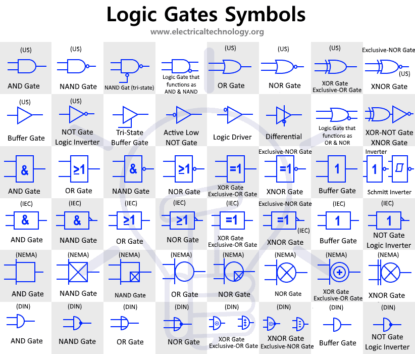
Digital Logic Gates Symbols Electronic Electrical Symbols

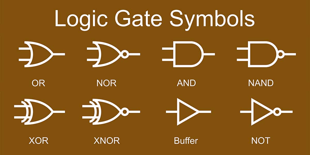
Small Logic Gates The Building Blocks Of Versatile Digital Circuits Part 1 Nuts Volts Magazine

Logic Gates Computer Science Gcse Guru
There are numerous signs and symbols ranging from the simple addition concept sign to the complex integration concept sign.

Logic gate symbols. Every Logic gate has a graphical representation or symbol associated with it. The data are the binary ones. Below is an image which shows the graphical symbols and truth tables associated with.
Download Logic Gate Simulator for free. In the case if any of the input has binary zero then the output we got will be binary 0. Logic Gate Simulator is an open-source tool for experimenting with and learning about logic gates.
The rules of logic give precise meaning to mathematical statements. -The XNOR gate negated XOR gives an output of 1 both inputs are same and 0 if both are different. You can compare the outputs of different gates.
EO 11 IDENTIFY the symbols used on logic diagrams to represent the following components. Number of phase possible 2 n 2 2 4. XNOR gate also known as Exclusive-NOR or Exclusive-Negative OR gate is A logic gate which produces High state 1 only when there is an even number of High state 1 inputs.
The basic logic gates are classified into seven types. An EXNOR logic gate is the opposite of the XOR gate. What is a Logic Gate.
Logic gates are small digital electronic devices that perform a Boolean function with two inputs and provide an output. Depending on the context the term may refer to an ideal logic gate one that has for instance zero rise time and unlimited fan-out or it may refer to a non-ideal physical device see. Logic Gate Simulator is an open-source tool for experimenting with and learning about logic gates.
Logic gates are symbols that can directly replace an expression in Boolean arithmetic. Based on the logical gate the logical operation differs and the output varies. NAND Gate NOR Gate are special logic gates.
AND gate OR gate XOR gate NAND gate NOR gate XNOR gate and NOT gate. Likewise if you input 0 it outputs as 1The NOT gate negates the values of data or signal in. The two logic levels are represented as binary numbers 0 and 1.
Logical 1 is true or high and logical 0 falls to false or low. The output of a gate can be a final result or it can be connected as an input to yet another gate. In logic a set of symbols is commonly used to express logical representation.
The working of these gate is such that at output terminal we will get binary 1 if and only if both the input are binary 1. Also note that a truth table with n inputs has 2 n rows. How do we know which relay contact is actuated by which.
Features include drag-and-drop gate layout and wiring and user created integrated circuits. These rules are used to distinguish between valid and invalid mathematical arguments. The following table lists many common symbols together with their name how they should be read out loud and the related field of mathematicsAdditionally the subsequent columns contains an informal explanation a short example the Unicode location the name for use in HTML documents and the LaTeX symbol.
Basic Logic Gates Operation What are the 7 Basic Logic Gates. The truth table is used to show the logic gate function. Each one has a different shape to show its particular function.
NAND Gate NOR Gate- Definitions. Azure Data SQL Samples. Here the list of mathematical symbols is provided in a tabular form and those notations are categorized according to the concept.
Table 2 is a summary truth table of the inputoutput combinations for the NOT gate together with all possible inputoutput combinations for the other gate functions. List of Mathematical Symbols. The circuit uses two diodes at input side.
Given this knowledge interpret the following ladder logic diagram. A NOT gate also often called Inverter is a logic gateEach NOT gate has only one input signal. We can extend the functionality of the gates we have seen so far by just attaching an inverter to them.
In all logic circuits 5 volts is represented as HIGH level logic and 0 volts or ground is represented as the LOW level logic. The resulting value from the expression equation is the output of the gate. NAND Gate NOR Gate are called as Universal Logic Gates or Universal Gates.
Logically with NOT gates the input and the output swap so if you input 1 it outputs as 0. A NOT gate often called an inverter is a nice digital logic gate to start with because it has only a single input with simple behaviorA NOT gate performs logical negation on its input. The multiple input gates are no different to the simple 2-input gates above So a 4-input AND gate would still require ALL 4-inputs to be present to produce the required output at Q and its larger truth table would reflect that.
Calculus and Analysis. The circuit design of OR gate by using diodes is given below. In other words if the input is true then the output will be falseSimilarly a false input results in a true output.
A logic gate is an idealized model of computation or physical electronic device implementing a Boolean function a logical operation performed on one or more binary inputs that produces a single binary output. Features include drag-and-drop gate layout and wiring and user created integrated circuits. It comes with a variety of components to design a logic gate circuit and later simulate it.
Apart from its importance in understanding mathematical reasoning logic has numerous applications in Computer Science varying from design of digital circuits to the construction of computer programs and verification of. The truth table for a NOT gate appears to the right. In ladder logic symbolism an electromechanical relay coil is shown as a circle and the contacts actuated by the coil as two parallel lines almost like a capacitor symbol.
These logic gates with their logic gate symbols and truth tables are explained below. 2-input logic gate truth tables are given here as examples of the operation of each logic function but there are many more logic gates with 3 4 even 8 individual inputs. For 2-input gate it can be interpreted as when both of the inputs are same then the output is High state and when the inputs are different then the output is Low state 0.
This chapter will review the symbols and conventions used on logic diagrams. EXCLUSIVE OR gate m. This logic gate consists of two input terminal and one output terminal.
You get basic gates NOT AND OR Inverter compound gates NAND NOR XOR XNOR and inputoutput gates usernumeric input usernumeric output clock period in ms comment etc to draw a.
Solved Autocad Electrical Logic Circuit Help Autodesk Community Autocad Electrical

Basic Logic Gates And Boolean Expressions Electrical Academia

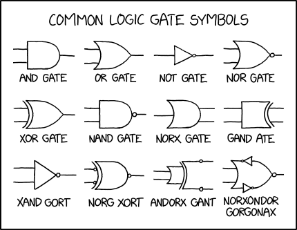
2497 Logic Gates Explain Xkcd

Electrical Symbols Logic Gate Diagram 2 Bit Alu Logic Gate Diagram Logic Gate Diagram Template Logic Gate Diagram

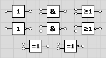
Logicly 1 1 Offers Iec Symbols And 3 Inputs On Logic Gates Logic Ly Blog

Logic Gates Or Icons Download Free Vector Icons Noun Project

Logic Gates Symbol Cad Block And Typical Drawing
1

